
Evaluation of Anchor Bolt Clearance Discrepancies
Project Description:
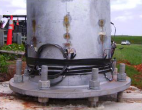
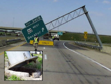
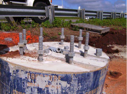
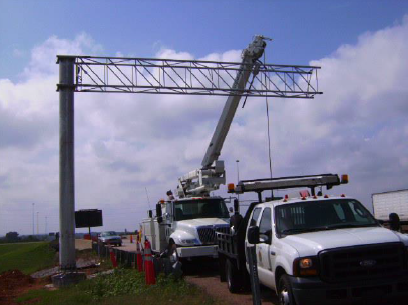
The clearance, or stand-off, distance for anchor bolts within a double nut moment joint is defined as the distance between the bottom of the base plate and the top of the concrete foundation. Evidence has shown that there currently exist structures with unleveled stand-off distances as a result from topographical boundaries at the construction site. This discrepancy has produced non-uniform stress distribution within the anchor bolt group due to service loading. Preliminary results of an in situ cantilevered sign support structure with this condition have shown that stress ranges for two of the anchor bolts within the group were higher than the constant amplitude fatigue limit (CAFL), which can potential be more severe for extreme wind loading events.
The main objective of this project is to investigate the effect of non-uniform stand-off distances on the stress distribution of the anchor bolts due to fatigue wind and extreme wind events. Analysis will focus on the stress distribution within the anchor bolt group as well as the area above the base plate-to-shaft weld. The main outcome of the project is to create limit-state design equations to be used in the event in which this condition is non-avoidable. The project will involve extensive finite element analysis (FEA) modelling and laboratory experimentation to determine the significance of this condition as well as a limit-state design approach.
Final Report
Evaluation of Anchor Bolt Clearance Discrepancies
Presentations:
- “Evaluation of Anchor Bolt Clearance Discrepancies”, presented at the 2014 UTC Conference for the Southeastern Region in Atlanta, Georgia, March 24-25, 2014.
Project Information Forms:
Describe Implementation of Research Outcomes (or why not implemented) :
The main outcome of the project is to create limit-state design equations to be used for the design of double nut moment joints with non-uniform stand-off distances. Implementation of the project will involve three specific objectives. A description of the up-to-date progress within each of the specific objectives is provided below.
Specific Objective #1
Understand the mechanics behind the stress distribution within an anchor bolt group with non-uniform stand-off distances using experimentally collected data for the stated connection obtained with ALDOT/UAB Project # 930-683, Design of Overhead Sign Structures for Fatigue Loads, to develop limit-state design equations.
Current Implementation of the Specific Objective
The implemented work is this project can be summarized as follows:
- Review of the design of anchor bolts according to AASHTO Standard Specifications 2013.
- Experimental data analysis from Project #930-683
- Review of past research regarding the design of anchor bolts according to shear and bending
Specific Objective #2
Finite element analysis (FEA) modeling of the connection to test the mechanical relationships for the stated connection, as well as other connections to understand the significance and severity this condition imposes on the anchor bolts and the area above the base plate-to-shaft weld.
Current Implementation of the Specific Objective
- Review of past research regarding FEA of anchor bolt connections.
- Identifying element types (i.e., shell, solid, beam elements) that will be most appropriate and accurate for the objective.
- Conducting a Design of Experiment (DoE) for altering base plate pitch—parameters that are directly related to uneven anchor bolt stand-off distances.
- Investigating other parameters to be used in the DoE analysis based on the mechanics analysis of the experimental data that are most influential to uneven anchor bolt stand-off distances (i.e., base plate thickness, number of anchor bolts, anchor bolt diameter).
Specific Objective #3
Validation of the mechanic relationships and FEA modeling through laboratory experimentation of the stated connection to test the limit-state design equations.
- Development of the test setup, instrumentation, number of specimens, and testing procedures of the specimen.
- An example of the test setup analysis involved an overturning check of the steel frame to identify the overturning load in order to be avoided during the test, and review the design of concrete block according to ACI 318 Appendix D.
- Design and failure checks of the concrete block—a specific component of the test setup—was conducted.
- Determination of the procedure that will be used to apply the inclination of the concrete surface to produce uneven standoff distances in the experimentation is shown by the contraption in Figure 6, in the June 2014 Project Information Form.
- A finite element model was implemented by using SAP software to identify the straining actions on the anchor bolts as well as studying the behavior of the structure due to loading.
Photos 1 through 9 provided courtesy of Ian Hosch of UAB, with the exception of photo 7, taken from Fouad, H.F., Sullivan, A., Calvert, E.A., and Hosch, I.E., (2009), "Design of overhead sign structures for fatigue loads." Project Number 930-680, Alabama Department of Transportation (ALDOT).
Impacts/Benefits of Implementation (actual, not anticipated):
The important specifics of the theoretical and experimental testing are near completion. This has helped the research team to identify important parameters necessary to complete the project objective. Most important of these was the development and design of the experimental test setup.
Images:


Principal Investigator(s):
Principal Investigator(s) Contact Information:
hoschi38@uab.edu
University(ies):
University of Alabama at Birmingham
Start and End Dates:
TBD
Topic:
State-of-Good-Repair
Lamar Allen Sustainable Education Building, 788 Atlantic Drive, Atlanta, GA 30332-0355 | P 404-894-2236 | F 404-894-2278 | nctspm@ce.gatech.edu
Visit GTI/UTC Site | School of Civil and Environmental Engineering at the Georgia Institute of Technology
Theme by Danetsoft and Danang Probo Sayekti inspired by Maksimer